Cortext M chip reset behaviour
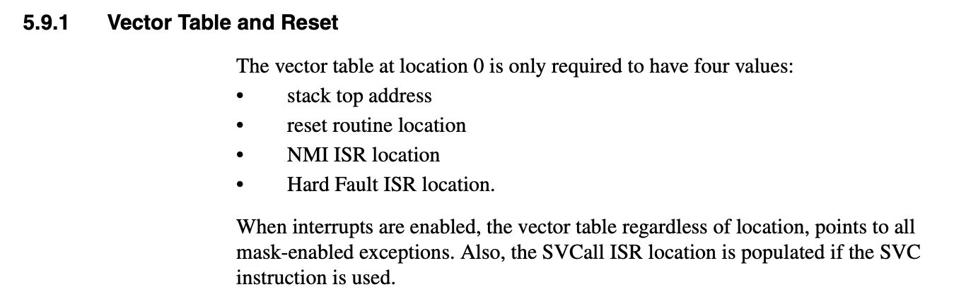
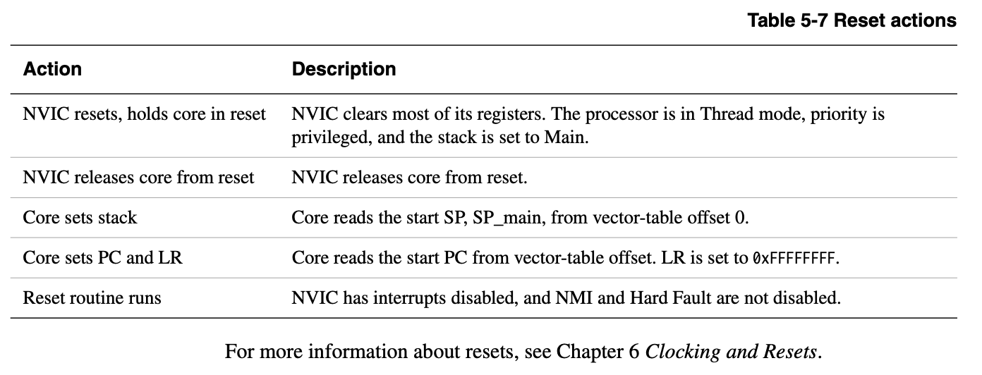
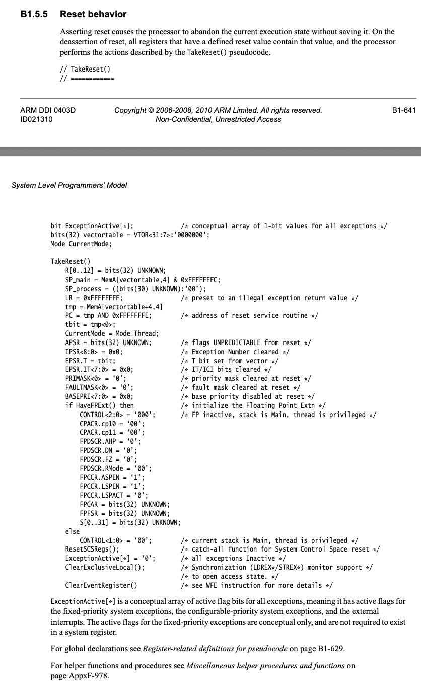
Upon power-on reset, the Cortex-M processor’s initial actions involve accessing the vector table • The core first reads the initial Stack Pointer (SP) from the first entry of the vector table (at address 0x00000000) • Then, the core reads the start Program Counter (PC), which is the reset vector, from the second entry of the vector table (at address 0x00000004) The Link Register (LR) is also set to 0xFFFFFFFF • Execution then begins at the address pointed to by the reset vector.
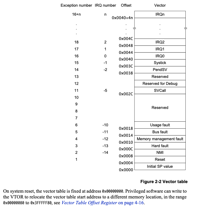
While the vector table is initially at 0x00000000, its location can be changed by writing to the Vector Table Offset Register (VTOR). This allows for relocating the vector table to a different memory location, such as SRAM, for performance optimization or to enable dynamic changes. When setting the offset in the VTOR, the table base must be aligned based on the number of exceptions supported, with a minimum alignment of 32 words (128 bytes) for up to 16 interrupts. For a larger number of interrupts, the alignment must be to the next power of two in terms of the number of words required.
 ddi0337e_cortex_m3_r1p1_trm (Section 5.9 Resets)
 DUI0553.pdf (Section 2.3.4 Vector Table)
 DDI0403D_arm_architecture_v7m_reference_manual (Section B1.5.5 Reset behaviour)
One special thing with vector table is that, the final compiled vector handler addresses are not power of two. This is because the bit[0] of these reset handlers are used for setting the EPSR.T bit on exception handlings.
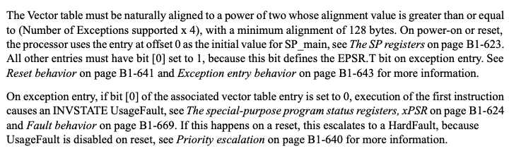 DDI0403D_arm_architecture_v7m_reference_manual (Section B1.5.3 Vector table)
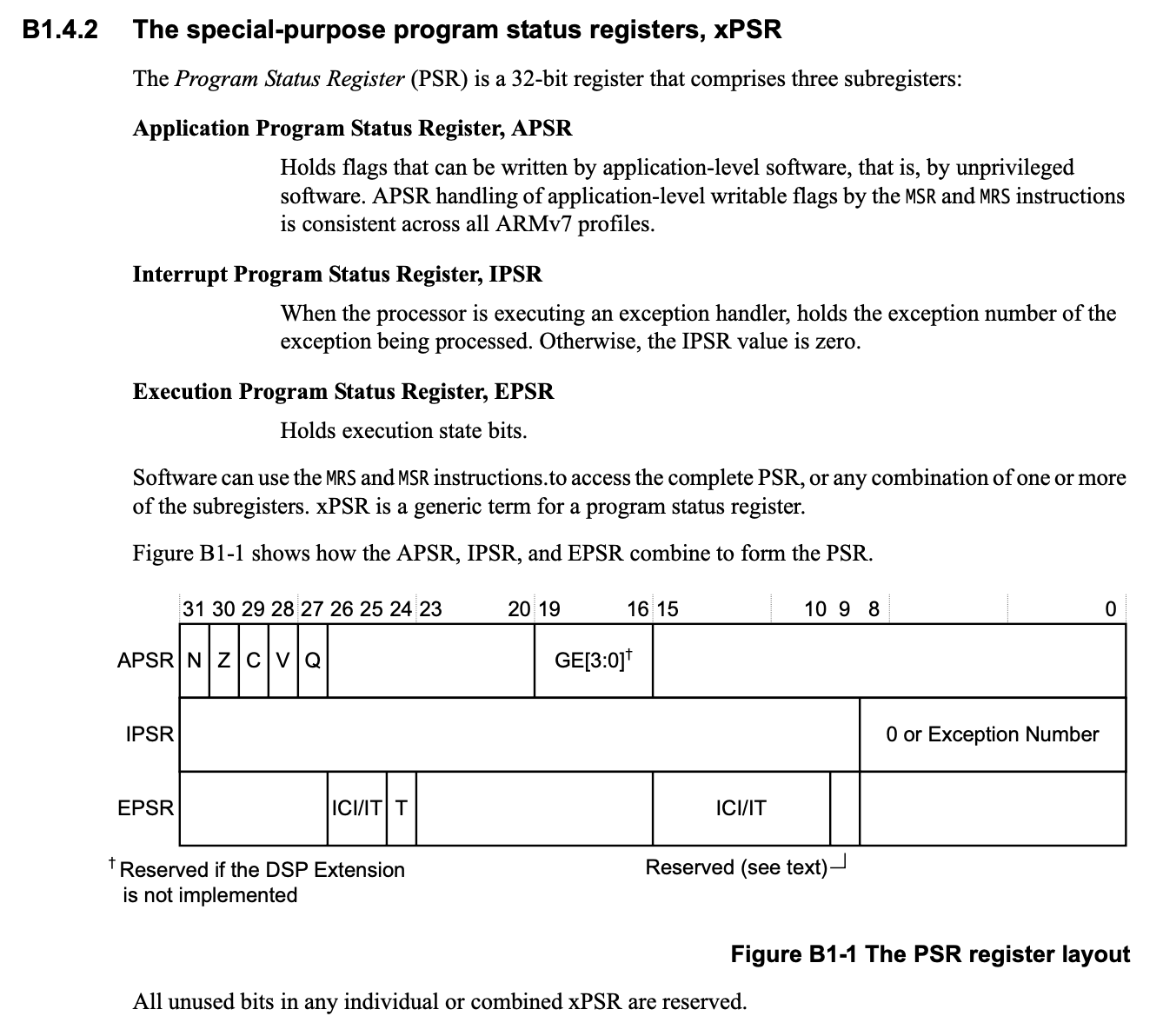
This kind of bring up the question what is the ESPR register?
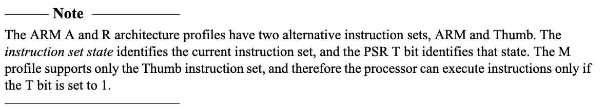
Okay so it is the thumb state, but why does the reset need to enable thumb instructions.
 DDI0403D_arm_architecture_v7m_reference_manual (Section B1.4.2 The special-purpose program status registers, xPSR)
Okay, this is actually news to me!